
- Arduino stepper motor serial control cable how to#
- Arduino stepper motor serial control cable software#
- Arduino stepper motor serial control cable code#
- Arduino stepper motor serial control cable Pc#
- Arduino stepper motor serial control cable series#
* This is a free software with NO WARRANTY. * Unipolar stepper motor speed and direction control with Arduino
Arduino stepper motor serial control cable code#
In this example I used Arduino stepper motor library (built-in) which simplifies the code, it’s included in the code using the following line: Stepper motor control with Arduino and joystick code: Using the X-axis and the Y-axis potentiometers we can control two stepper motors independently. The switch pin (SW) is not used in this example. The output of the X-axis potentiometer (VRX) is connected to Arduino analog pin A0, Y-axis potentiometer output (VRY) can also be used. SW is the push button terminal (the other terminal is connected to GND). The joystick board has 5 pins: GND, +5V, VRX, VRY and SW where: The control lines (IN1, IN2, IN3 and IN4) of this board are connected to the Arduino as follows: The stepper motor is connected to the ULN2003A board which is supplied with external power source of 5V.
Arduino stepper motor serial control cable how to#
If you want to see the complete assembly where I used this circuit, you can follow this link where I explain how to build a robotic airsoft turret.And the following image shows fritzing circuit:
Arduino stepper motor serial control cable Pc#
Notice that the port BaudRate property is set to 9600 in both the program in the Arduino board and that in the PC program. Int pin1 = 22 int pdir = LOW void setup() p.Write(val, 0, 2) p.Close() The program for the Arduino board is as follows:

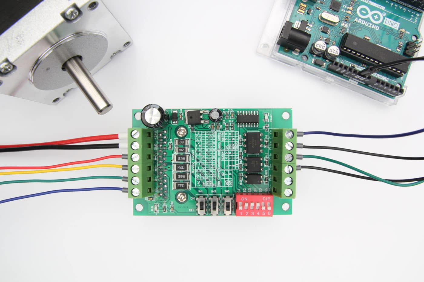
I used the pins 22, 24, 26 and 28, but you can use those you want instead. The inputs S1 to S4 are connected to 4 output pins of the Arduino board. In this example I only need 4, so I only show the scheme for this amount, the board also allows you to move motors with 5 terminals all you have to do is to add another switch to the scheme. In the board you can see five transistors. This is the scheme of the board: Board circuit scheme This is the board that I have mounted: Motor controller boardĮach switch is composed of a 2N2222 transistor, a BA 158 diode and a 1K resistor, as simple as that. This board is a hello world for running a basic stepper motor board.
Arduino stepper motor serial control cable series#
In the case of this motor, I used 12V, which is standard in this type of engine.Īs the work of control and timing is all done through software, either on the Arduino board or in the PC program, all you need is a series of switches that allow you to control the 12 volts needed by the motor using the 5 volts of the Arduino outputs. The bridge board is connected to a computer via a FTDI cable. To find out the order in which we polarize these wires, simply connect the common terminal to ground and keep trying to passing a current pulse through the other wires until you get four movements in the same direction. In this case, I have a common terminal and four cables that connect to each coil. Resistance will be the same between any two coil terminals, but it will be around one half between one of these terminals and the common one. This is pretty simple you only need a multimeter to measure the resistance between each pair of wires. The problem in this case is to find out which cables polarize the coils and what the common wire is. I got it from an old hard drive, on a PC that had nothing less than the processor 8086, but it is similar to others that can be found in the market without problems. That which I will use in this article is a unipolar one, which is the easiest to control, since it is only necessary to activate in an order determined the different coils for the motor to move in the desired direction.

The model of Arduino board I used is the Arduino MEGA, which provides lots of inputs and outputs, although you can use any other board model connected to the computer with a USB connection. In this link you can download the source code and executable of the StepByStepMotorArduino project, written with Visual Studio 2013. In this article I will show how to build a simple controller to handle one of these motors through the Arduino board, along with a sample program written in CSharp that allows you to operate the motor from the computer where the plate is connected. This makes these engines very suitable for mounting them in devices which perform movements that required high precision. Martes, 1 de noviembre de 2016 Stepper motor controller with ArduinoĪ stepper motor is a kind of motor that, instead of rotating continuously in one direction, allows rotate in very small steps and stop and change direction very quickly, without problems of inertia.


 0 kommentar(er)
